01
Wafer assembly
WaferClamped between two existing line flanges, with or without mounting accessories. The shorter and lighter installation.
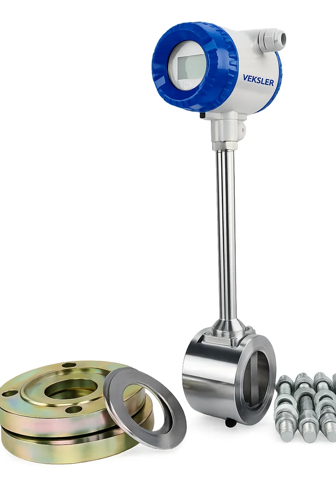
A solid-state flow meter with no moving parts. It creates vortices in the flow and uses their frequency to calculate flow in liquids, gases or steam.
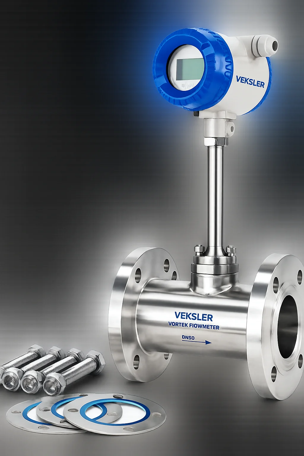
A solid-state flow meter with no moving parts. It creates vortices in the flow and uses their frequency to calculate flow in liquids, gases or steam.
With no moving parts, the sensor is largely unaffected by medium temperature, pressure or composition, giving high accuracy, a wide range ratio and low maintenance across production and process industries.
Twenty-one calibres from DN15 to DN1000, for petroleum, chemical, power and process industries.
Precision to ±1%R with a wide, stable rangeability of 1:6 to 1:25.
Nothing to wear, so mechanical stability stays high and maintenance stays low.
One sensor line measures gas, liquid and steam across DN15 to DN1000.
EXiaIICT4 Ga certified for safe use in hazardous process areas.
Standard specification unless otherwise specified at order
| Nominal diameter | DN15 – DN300 (in-line); DN300 – DN1000 (plug-in) |
|---|---|
| Nominal pressure | DN15–DN200: 4.0 MPa · DN250–DN300: 1.6 MPa |
| Medium temperature | −20 °C ~ 100 / 250 / 330 °C (piezoelectric) |
| Wetted material | SS 304, SS 316 |
| Accuracy class | ±1%R, ±1.5%R · Plug-in: ±2.5%R |
| Rangeability | 1:6 to 1:25 |
| Power supply | 230 V AC or 24 V DC |
| Output signal | Pulse (square wave) or 4~20 mA current; RS485 optional |
| Protection level | Ordinary IP65; submersible version IP68 |
| Environmental conditions | −20 °C ~ 55 °C, 5% ~ 90% RH, 86~106 kPa |
| Explosion protection | EXiaIICT4 Ga |
Applicable media: gas, liquid and steam. Transmission distance up to 1500 m for current output, 300 m for pulse output. Output signal, accuracy class and flange rating can be specified at the time of order.
By nominal calibre, in cubic metres per hour. Bracketed calibres are plug-in type.
| Calibre (mm) | Liquid (m³/h) | Gas (m³/h) |
|---|---|---|
| 15 | 0.8 ~ 5 | 6 ~ 18 |
| 20 | 1 ~ 8 | 8 ~ 40 |
| 25 | 1.5 ~ 12 | 10 ~ 70 |
| 32 | 2 ~ 20 | 15 ~ 120 |
| 40 | 3 ~ 30 | 25 ~ 200 |
| 50 | 5 ~ 50 | 30 ~ 300 |
| 65 | 8 ~ 80 | 50 ~ 500 |
| 80 | 12 ~ 120 | 80 ~ 800 |
| 100 | 20 ~ 200 | 120 ~ 1200 |
| 125 | 30 ~ 300 | 160 ~ 1600 |
| 150 | 40 ~ 400 | 250 ~ 2500 |
| 200 | 80 ~ 800 | 400 ~ 4000 |
| 250 | 120 ~ 1200 | 600 ~ 6000 |
| 300 | 200 ~ 2000 | 1000 ~ 10000 |
| (300) | 100 ~ 1500 | 1560 ~ 15600 |
| (400) | 180 ~ 3000 | 2750 ~ 27000 |
| (500) | 300 ~ 4500 | 4300 ~ 43000 |
| (600) | 450 ~ 6500 | 6100 ~ 61000 |
| (800) | 750 ~ 10000 | 11000 ~ 110000 |
| (1,000) | 1200 ~ 1700 | 17000 ~ 170000 |
| > (1,000) | Negotiate | Negotiate |
Select on working condition flow, not pipe diameter. Sizing to the pipeline rather than the actual process flow is the most common cause of measurement error; converting the application's flow to working condition and checking it against this table keeps the reading in the instrument's optimal mid-range.
Supplied with flange, gasket and bolt kit for installation. Both assemblies share the same sensing element and performance parameters.
Clamped between two existing line flanges, with or without mounting accessories. The shorter and lighter installation.
Flanged body bolted directly into the run, with or without mounting accessories.
Send the fluid, flow range, line size, pressure and temperature. We will check the velocity range and confirm the right meter size and output.